Showing posts with label Analog Electronics. Show all posts

Monday, 10 October 2011

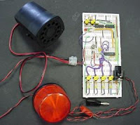
Make your own Burglar Alarm


Let’s begin!

Materials


  1. Insulated Wire
    • Get 4 strands of wire, each 1 foot in length
    • You can find the wires around the house, inside battery-operated appliances that no longer work. Make sure that your parents give you permission to take them apart.
    • You can also buy the wires and other supplies listed from a Radio Shack, a hardware store, or the electrical section of big stores like Walmart.
    • Note: In order to make this alarm, you will need to peel off the rubber/plastic insulation from two of the wires. Try to peel the wires before starting this lesson. If it is too difficult for you, then you can buy non-insulated wire that does not need peeling.
  2. 1.5-volt battery.
  3. Kite string or button-and-carpet thread, 3-5 feet long.
  4. Scissors
  5. Electrical tape
  6. 1.5-volt mini-buzzer
  7. Spring-type wooden clothes pin
  8. A scrap piece of board or plywood 4 inches by 12 inches or bigger.
  9. Super Glue

Principles

The burglar alarm is made of three parts:
  1. The device that makes noise - a buzzer
  2. The battery
  3. The buzzer switch

The Buzzer

We cannot have an alarm without something that makes sounds. That is why we use a buzzer, which is something that makes a loud sound. To make the sound, the buzzer needs to be connected to the battery.

The Battery

The battery is very important to the alarm. For the buzzer to work, it needs energy. This energy comes from the battery. If the buzzer is not connected to the battery, it will not work. You have a switch to control this connection.

The Buzzer Switch

See how the buzzer works by connecting your 1.5-volt battery to the buzzer directly. (The buzzer should come with two different wires. If the wire is insulated, you will need to peel a small length so that you are able to see the metal wire inside.) Get two other pieces of wire and connect them to opposite ends of the battery. Connect one wire to (+) and the other to (-). The battery should have the (+) and (-) labeled. Also, if you look closely, there is a (+) and (-) on the battery that you bought.
You may want to use electrical tape to hold the wires in place on the battery.
Connect the buzzer’s wires and the battery’s wires by twisting them, just like in the diagram 1. The buzzer should be making a sound; if it does not, check the connections at the ends of the wires to the battery.

Question :
  • What happens when you disconnect a wire from the buzzer?
    Now, connect it again as often as you want and see how the buzzer turns on and off. By connecting and disconnecting the wires, what you have made is called a switch.
When you disconnect a wire and the buzzer stops sounding, we say that the switch is open. When it is open, no energy from the battery reaches the buzzer.
When you connect the wire and the buzzer sounds, we say that the switch is closed. When it is closed, the energy from the battery reaches the buzzer.

Monday, 12 September 2011

Switching Regulators

Step-Up and Inverting Switching Regulators

             The switching regulator shown in Figure 9-3 is a step-down regulator—Vo is smaller in value than VIN. Figure 9-5 shows two other types of regulators, a step-up and an inverting regulator. The step-up regulator produces a regulated voltage VO that is greater in value than VIN, while the inverting regulator produces a Vo that is inverted in polarity from VIN. A positive VIN produces a negative Vo.

Switching Regulator Design
                The design of switching regulators can be accomplished in a number of ways, but they all include the inductor as the temporary energy storage element and large storage capacitors. The inductor and capacitor(s) cannot be integrated into ICs; therefore they are external to any ICs used. Any of the other components, depending on the current and voltage requirements, can at least be partially integrated circuits. For example, if the current handling is within the range of 1–2 amperes, all of the error amplifier, PWM circuit, oscillator, and the control element can be one IC. With higher current requirements, external heat-sinked driver packages can be used for the control element. Resistor dividers are always used to sample the output voltage to feed back to the error amplifier.


Transformed PWM Regulators
In a different design than that shown in Figure 9-3, the PWM circuit, which contains the error amplifier, oscillator, voltage reference and some protection circuits, is used as an AC source. This AC source is transformedto the desired voltage, filtered, and fed back to the error amplifier to close the regulation loop. Such a regulator is similar to the ones described because it uses PWM pulses for regulation control, but it does not utilize the inductor as a temporary storage element. An increased pulse width (larger ON time) will increase the voltage out from the transformed source; while a decreased pulse width decreases the voltage output.

Switching Regulators

Step-Up and Inverting Switching Regulators

             The switching regulator shown in Figure 9-3 is a step-down regulator—Vo is smaller in value than VIN. Figure 9-5 shows two other types of regulators, a step-up and an inverting regulator. The step-up regulator produces a regulated voltage VO that is greater in value than VIN, while the inverting regulator produces a Vo that is inverted in polarity from VIN. A positive VIN produces a negative Vo.

Switching Regulator Design
 
                The design of switching regulators can be accomplished in a number of ways, but they all include the inductor as the temporary energy storage element and large storage capacitors. The inductor and capacitor(s) cannot be integrated into ICs; therefore they are external to any ICs used. Any of the other components, depending on the current and voltage requirements, can at least be partially integrated circuits. For example, if the current handling is within the range of 1–2 amperes, all of the error amplifier, PWM circuit, oscillator, and the control element can be one IC. With higher current requirements, external heat-sinked driver packages can be used for the control element. Resistor dividers are always used to sample the output voltage to feed back to the error amplifier.


Transformed PWM Regulators
In a different design than that shown in Figure 9-3, the PWM circuit, which contains the error amplifier, oscillator, voltage reference and some protection circuits, is used as an AC source. This AC source is transformedto the desired voltage, filtered, and fed back to the error amplifier to close the regulation loop. Such a regulator is similar to the ones described because it uses PWM pulses for regulation control, but it does not utilize the inductor as a temporary storage element. An increased pulse width (larger ON time) will increase the voltage out from the transformed source; while a decreased pulse width decreases the voltage output.

Actual Regulation

 
               Producing more or less voltage across the load is based upon modulating the time that the control element is closed. This is accomplished by the pulse-width modulator (PWM) driven by the error amplifier. An oscillator produces the start of pulses at a constant rate, but the end of the pulse is determined by the voltage supplied by the error amplifier. The relationship of the control voltage from the error amplifier to the pulse width that turns on the switch is shown in Figure 9-4. Note the center of the figure has a line that represents a constant level of the control voltage B that is the nominal voltage level at the rated current output. The pulse width for this control voltage is shown as width C. When the demand for current increases, the pulse width increases because the ON time of the pulse is increased. More energy is stored in the inductor so that the increased current can be supplied and the voltage maintained. The integration of the current pulses by the output filter establishes the output voltage level. More ON time in the pulses produces a higher voltage, less ON time in the pulses produces a lower voltage. As shown in Figure 9-4, when minimum current is required the pulse width is narrow with a short ON time.

Likewise, when maximum current is required the pulse width is wide with a long ON time. Here is a description of the regulation in simple terms. When the load demands more current the output voltage tends to decrease. This voltage decrease is sampled and converted to an error voltage that increases the control voltage B and increases the ON time of the pulses. The increase in ON time supplies the increased current and raises the output voltage to its required value. A load that demands less current would tend to increase the output voltage. The voltage increase is sampled and converted to an error voltage that decreases the control voltage B and decreases the ON time of the pulse. The decrease in ON time of the pulses lowers the voltage and satisfies the demand for less current. Switching regulators operate at frequencies from 100 kHz to several million cycles/sec. Because of the range of frequencies and the switching action, there is some concern about RFI energy; and attention must be paid to the shielding of sensitive circuits.

Newest